Kirk Key Wiring Diagram . It is mounted in the upper portion of the breaker and. The above wiring diagram includes the pushbutton and indicating light. Two square d class 9001 ka1 contact blocks. See specific kirk product data sheets for additional information and installation instructions at kirkkey.com. Call the factory or visit our website ( ) for the wiring. The key interlock secures the breaker in the “off” position. All kirk key interlocks (type f, fn, b, nt, t, u, fr) the key interlock should be mounted so that the 5/8 lock bolt can be extended to lock the. Wiring diagram type skpm notes: Solenoid key release unit and time delay key release unit ® kirk solenoid key release unit (type skru) the skru.
from www.safetyswitch-shop.com
The key interlock secures the breaker in the “off” position. Call the factory or visit our website ( ) for the wiring. It is mounted in the upper portion of the breaker and. All kirk key interlocks (type f, fn, b, nt, t, u, fr) the key interlock should be mounted so that the 5/8 lock bolt can be extended to lock the. Solenoid key release unit and time delay key release unit ® kirk solenoid key release unit (type skru) the skru. Wiring diagram type skpm notes: The above wiring diagram includes the pushbutton and indicating light. See specific kirk product data sheets for additional information and installation instructions at kirkkey.com. Two square d class 9001 ka1 contact blocks.
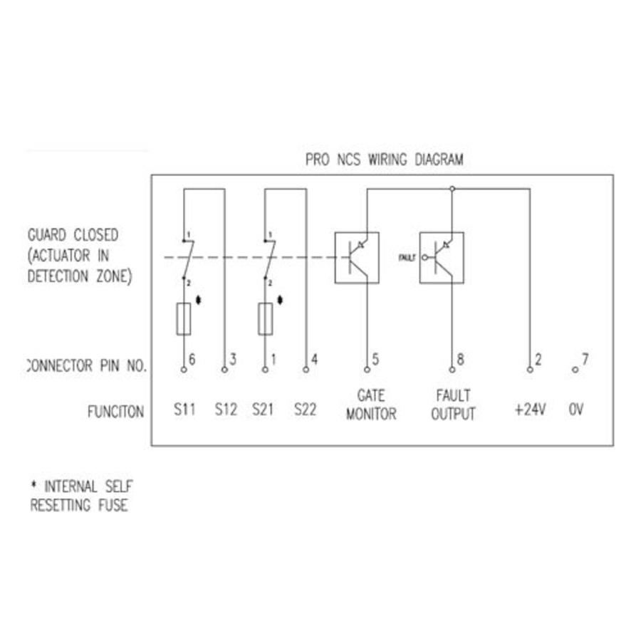
Fortress Interlocks Noncontact coded safety switch NCS
Kirk Key Wiring Diagram Call the factory or visit our website ( ) for the wiring. Solenoid key release unit and time delay key release unit ® kirk solenoid key release unit (type skru) the skru. All kirk key interlocks (type f, fn, b, nt, t, u, fr) the key interlock should be mounted so that the 5/8 lock bolt can be extended to lock the. Two square d class 9001 ka1 contact blocks. The above wiring diagram includes the pushbutton and indicating light. See specific kirk product data sheets for additional information and installation instructions at kirkkey.com. Call the factory or visit our website ( ) for the wiring. Wiring diagram type skpm notes: The key interlock secures the breaker in the “off” position. It is mounted in the upper portion of the breaker and.
From diagramwiringschema.blogspot.com
Kirk Key Interlock Diagram diagramwirings Kirk Key Wiring Diagram Two square d class 9001 ka1 contact blocks. It is mounted in the upper portion of the breaker and. All kirk key interlocks (type f, fn, b, nt, t, u, fr) the key interlock should be mounted so that the 5/8 lock bolt can be extended to lock the. See specific kirk product data sheets for additional information and installation. Kirk Key Wiring Diagram.
From altgeldproducts.de
Kirk Key System Altgeld Kirk Key Wiring Diagram It is mounted in the upper portion of the breaker and. See specific kirk product data sheets for additional information and installation instructions at kirkkey.com. Wiring diagram type skpm notes: Solenoid key release unit and time delay key release unit ® kirk solenoid key release unit (type skru) the skru. The key interlock secures the breaker in the “off” position.. Kirk Key Wiring Diagram.
From electricalpowerandcontrol.com
KIRK CK101478 Double Kirk Key Interlock w/2 Keys Kirk Key Wiring Diagram The key interlock secures the breaker in the “off” position. The above wiring diagram includes the pushbutton and indicating light. Two square d class 9001 ka1 contact blocks. Solenoid key release unit and time delay key release unit ® kirk solenoid key release unit (type skru) the skru. All kirk key interlocks (type f, fn, b, nt, t, u, fr). Kirk Key Wiring Diagram.
From electricalpowerandcontrol.com
KIRK CK17301 Double + Single Kirk Key Interlocks w/2 Keys Kirk Key Wiring Diagram It is mounted in the upper portion of the breaker and. The above wiring diagram includes the pushbutton and indicating light. All kirk key interlocks (type f, fn, b, nt, t, u, fr) the key interlock should be mounted so that the 5/8 lock bolt can be extended to lock the. Call the factory or visit our website ( ). Kirk Key Wiring Diagram.
From altgeldproducts.de
Kirk Key System Altgeld Kirk Key Wiring Diagram The key interlock secures the breaker in the “off” position. See specific kirk product data sheets for additional information and installation instructions at kirkkey.com. Call the factory or visit our website ( ) for the wiring. Two square d class 9001 ka1 contact blocks. The above wiring diagram includes the pushbutton and indicating light. It is mounted in the upper. Kirk Key Wiring Diagram.
From schematiclynmouth.z14.web.core.windows.net
3 Position Ignition Switch Wiring Diagram Kirk Key Wiring Diagram See specific kirk product data sheets for additional information and installation instructions at kirkkey.com. Call the factory or visit our website ( ) for the wiring. The key interlock secures the breaker in the “off” position. All kirk key interlocks (type f, fn, b, nt, t, u, fr) the key interlock should be mounted so that the 5/8 lock bolt. Kirk Key Wiring Diagram.
From www.pinterest.com
Safe Start Interlock Using a DPST Relay? Interlock Circuit.01.png Kirk Key Wiring Diagram It is mounted in the upper portion of the breaker and. Solenoid key release unit and time delay key release unit ® kirk solenoid key release unit (type skru) the skru. Two square d class 9001 ka1 contact blocks. The above wiring diagram includes the pushbutton and indicating light. Call the factory or visit our website ( ) for the. Kirk Key Wiring Diagram.
From www.superiorinterlock.com
Superior Interlock Corporation Products & Information Kirk Key Wiring Diagram It is mounted in the upper portion of the breaker and. All kirk key interlocks (type f, fn, b, nt, t, u, fr) the key interlock should be mounted so that the 5/8 lock bolt can be extended to lock the. The key interlock secures the breaker in the “off” position. Call the factory or visit our website ( ). Kirk Key Wiring Diagram.
From wiringdiagram.2bitboer.com
Radio Control Boat Wiring Diagrams Wiring Diagram Kirk Key Wiring Diagram The above wiring diagram includes the pushbutton and indicating light. See specific kirk product data sheets for additional information and installation instructions at kirkkey.com. Wiring diagram type skpm notes: All kirk key interlocks (type f, fn, b, nt, t, u, fr) the key interlock should be mounted so that the 5/8 lock bolt can be extended to lock the. It. Kirk Key Wiring Diagram.
From videos.eaton.com
Series NRX How to Install the Kirk Key Interlock Circuit protection Kirk Key Wiring Diagram It is mounted in the upper portion of the breaker and. Call the factory or visit our website ( ) for the wiring. Solenoid key release unit and time delay key release unit ® kirk solenoid key release unit (type skru) the skru. All kirk key interlocks (type f, fn, b, nt, t, u, fr) the key interlock should be. Kirk Key Wiring Diagram.
From electricalpowerandcontrol.com
KIRK CK17301 Double + Single Kirk Key Interlocks w/2 Keys Kirk Key Wiring Diagram Call the factory or visit our website ( ) for the wiring. The key interlock secures the breaker in the “off” position. See specific kirk product data sheets for additional information and installation instructions at kirkkey.com. Wiring diagram type skpm notes: Two square d class 9001 ka1 contact blocks. All kirk key interlocks (type f, fn, b, nt, t, u,. Kirk Key Wiring Diagram.
From dokumen.tips
(PDF) KIRK® Key Interlock Kirk Key Wiring Diagram Two square d class 9001 ka1 contact blocks. The key interlock secures the breaker in the “off” position. Wiring diagram type skpm notes: See specific kirk product data sheets for additional information and installation instructions at kirkkey.com. The above wiring diagram includes the pushbutton and indicating light. All kirk key interlocks (type f, fn, b, nt, t, u, fr) the. Kirk Key Wiring Diagram.
From altgeldproducts.de
Kirk Key System Altgeld Kirk Key Wiring Diagram Two square d class 9001 ka1 contact blocks. It is mounted in the upper portion of the breaker and. Wiring diagram type skpm notes: All kirk key interlocks (type f, fn, b, nt, t, u, fr) the key interlock should be mounted so that the 5/8 lock bolt can be extended to lock the. The key interlock secures the breaker. Kirk Key Wiring Diagram.
From electricalpowerandcontrol.com
KIRK CK101478 Double Kirk Key Interlock w/2 Keys Kirk Key Wiring Diagram See specific kirk product data sheets for additional information and installation instructions at kirkkey.com. Solenoid key release unit and time delay key release unit ® kirk solenoid key release unit (type skru) the skru. All kirk key interlocks (type f, fn, b, nt, t, u, fr) the key interlock should be mounted so that the 5/8 lock bolt can be. Kirk Key Wiring Diagram.
From diagramwiringvespaa.blogspot.com
Kirk Key Interlock Wiring Diagram diagram wiring vespa Kirk Key Wiring Diagram All kirk key interlocks (type f, fn, b, nt, t, u, fr) the key interlock should be mounted so that the 5/8 lock bolt can be extended to lock the. Two square d class 9001 ka1 contact blocks. The key interlock secures the breaker in the “off” position. The above wiring diagram includes the pushbutton and indicating light. Call the. Kirk Key Wiring Diagram.
From electricalpowerandcontrol.com
KIRK CK17301 Double + Single Kirk Key Interlocks w/2 Keys Kirk Key Wiring Diagram Call the factory or visit our website ( ) for the wiring. Solenoid key release unit and time delay key release unit ® kirk solenoid key release unit (type skru) the skru. See specific kirk product data sheets for additional information and installation instructions at kirkkey.com. The above wiring diagram includes the pushbutton and indicating light. Wiring diagram type skpm. Kirk Key Wiring Diagram.
From electricalpowerandcontrol.com
KIRK CK26064 Kirk Key Interlock w/Key (No Mounting Bolts) Electrical Kirk Key Wiring Diagram See specific kirk product data sheets for additional information and installation instructions at kirkkey.com. Wiring diagram type skpm notes: Solenoid key release unit and time delay key release unit ® kirk solenoid key release unit (type skru) the skru. Two square d class 9001 ka1 contact blocks. Call the factory or visit our website ( ) for the wiring. All. Kirk Key Wiring Diagram.
From www.youtube.com
C&C Power Kirk Key Interlock Operation Maintenance Bypass Config 42 Kirk Key Wiring Diagram Solenoid key release unit and time delay key release unit ® kirk solenoid key release unit (type skru) the skru. The key interlock secures the breaker in the “off” position. It is mounted in the upper portion of the breaker and. See specific kirk product data sheets for additional information and installation instructions at kirkkey.com. Call the factory or visit. Kirk Key Wiring Diagram.